Midnight Lightning
"How-To" Page
 Raised |
 Lowered |
Install a Big Boar Air Suspension
Disclaimer: I can not be held responsible for anyone screwing up their bike or accessories when attempting this modification.
While it worked well for me, I can't guarantee other people's workmanship or prevent their mistakes.
You undertake this at your own risk!
A new shock was something like $330 retail. Wow. If I was going to have to spend that much money, I may as well look at air suspension alternatives.
Plus, the thought appealed to me of being able to have the flexibility for both the lowered look when wanted, and having the bike raised higher for better cornering through the twisties. I did some research on the air suspension kits available and decided the Big Boar was for me (www.BikerBrackets.com).
Bought mine through Hellrisers: Suspension kit + remote + shipping = $760 total.
My bike's been lowered by the "flip" method for four years now (with the Eibach 1000 lb. spring).
I noticed lately that the rear shock seemed to be failing. 2-up riding was continually bottoming out and dragging pipes and frame....where before, it rarely did.
Click on any photo for a larger version.
|
The kit comes with instructions. Jeffrey Leitner (Biker Brackets' owner) hangs out on the Road Star Riders forum (see "Links" page), and he sent me a PDF copy so I could be familiar with the instructions prior to the kit arriving.
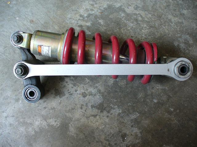
First step is to remove your existing shock assembly. The photo on the left shows the removed assembly. On the particular set-up I've been running for a cheap lowered look: stock dogbones, relay arm "flipped" (see "Flip" How-To), Eibach 1000 lb spring). |
|
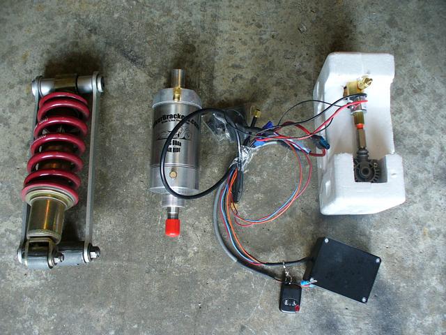
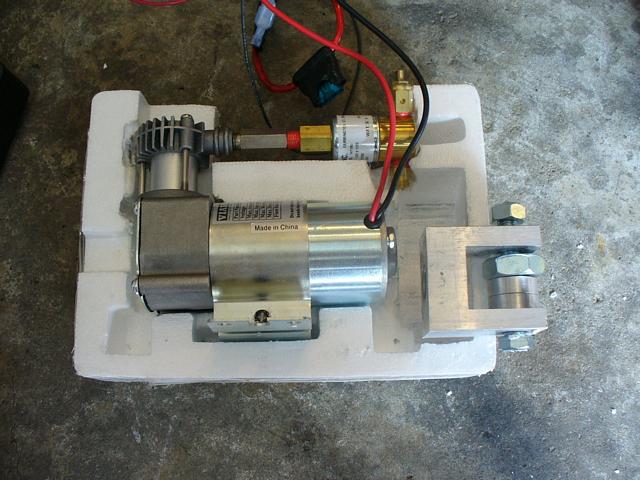
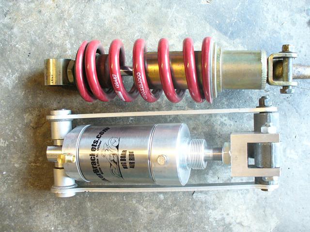
Here's the kit next to the shock assembly. I was a bit concerned because I didn't see the clevis (the U=shaped piece that bolts to the relay arm). |
|
Ah! It was inside the beadboard packing! |
|
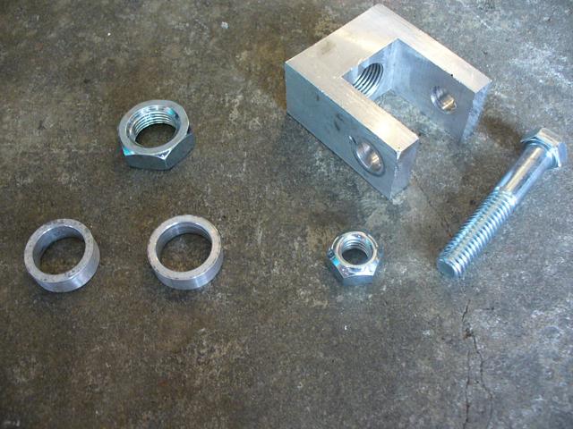
Here's the clevis. There are also two small spacers. They'll be used on the other end of the shock. |
|
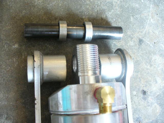
This shows where the two spacers will go, on the opposite end of the shock that has the clevis attached. |
|
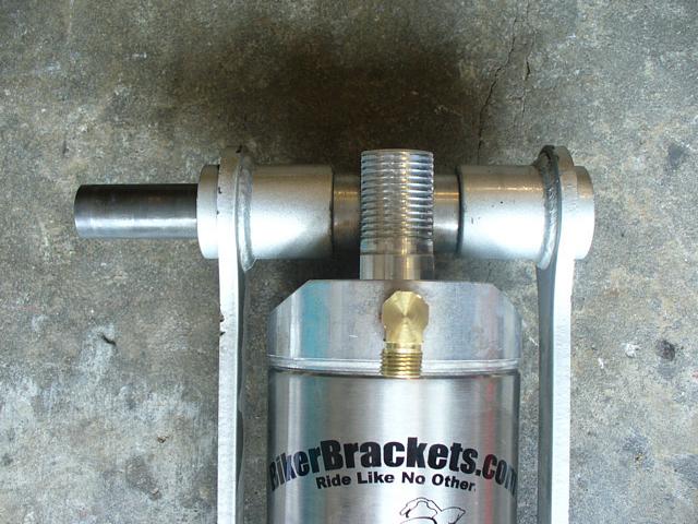
Assembling the spacers onto their end. |
|
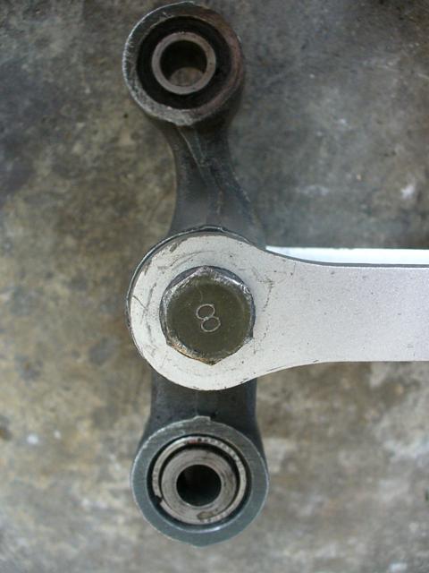
This photo just shows the geometry of how the relay arm looks when "flipped". Note how the upper portion curves toward the rear of the bike (to the left).
Not knowing how this would affect the new air suspension, I made the decision to first assemble the Big Boar with the relay arm un-flipped. Then see how the range of the upper and lower limits looked and worked. I could always change it later. |
|
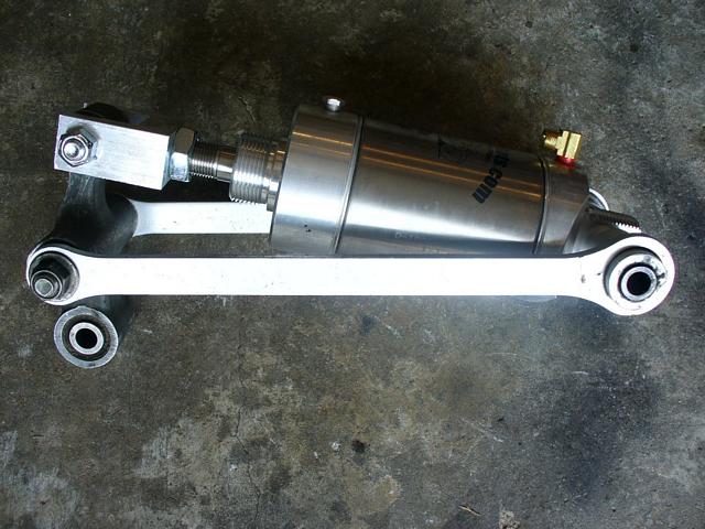
Top view of the assembled Big Boar cylinder. Note that I didn't screw the clevis down far at all onto the large threaded shaft of the air cylinder. Again...I have no idea what will work best for this set-up versus what I had before. Should I mount the clevis closer or farther from the cylinder? Should the relay arm be flipped or un-flipped?. These were two variables I just had to experiment with until I got what satisfied me (a decent raised height, but still a nice slammed look for the parking lot).
So...I went with the most conservative set-up first: You'll see what my final set-up decision is in a minute. |
|
Side view of the conservative set-up I just described in the last step. |
|
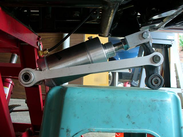
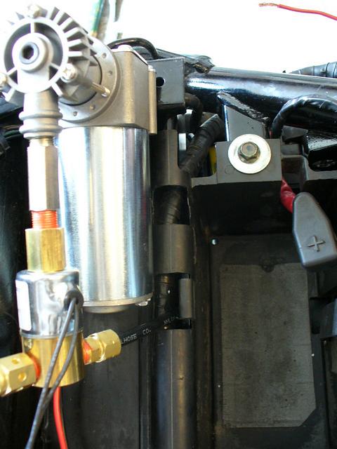
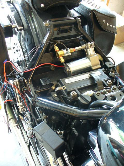
Before raising it completely into the bike, you need to attach the airline to the front of the air cylinder.
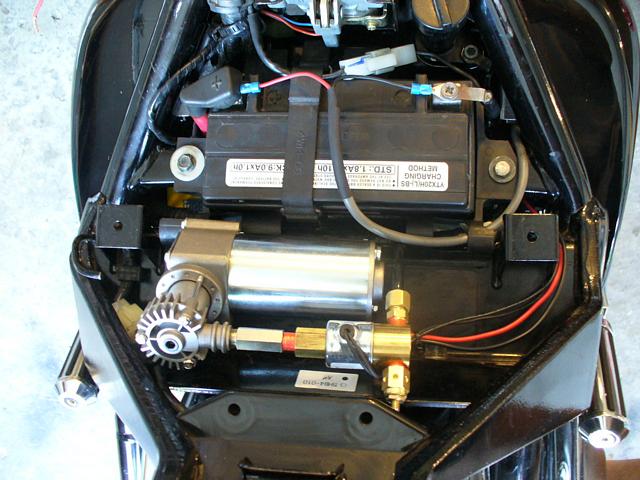
The air compressor mounts under your seat where your tool kit normally sits. You do lose the space for the tool kit when doing this mod! First you feed the air line down from behind the battery from under the seat (this will be more clear in the photos below). Then you attach the other end to the air cylinder. In order not to pull it out from where it comes up under the seat behind the battery, I propped the assembly up on a stool to attach the line to the cylinder. You can see the line here attached to the cylinder and running up under the bike to beneath the seat. The included instructions show where and how to route this line around your suspension's swing arm so it doesn't get pinched or rubbed. This is clearer in the color PDF instructions than it was in the included black-and-white paper instructions (same instructions - it's just that the paper version isn't in color). |
|
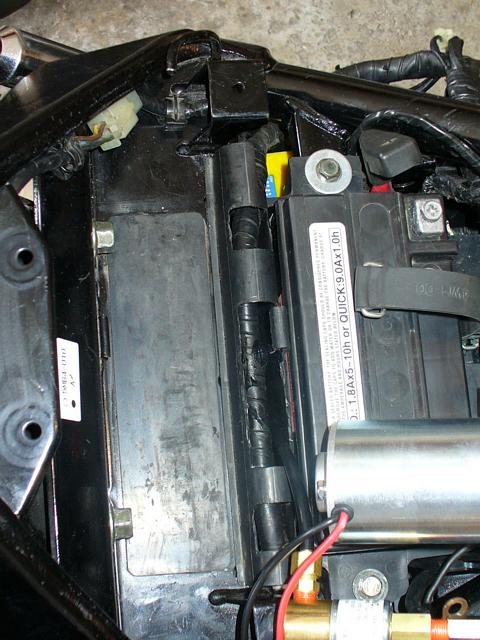
You can see here where the air line comes up behind the battery (the battery is removed in this photo). One problem though.... In order to get the air compressor completely under the seat horns (so the seat can mount properly), I need to shift the compressor and airline towards the right-hand side of the bike (down, in this particular photo). The plastic portion of the battery tray where the line comes up prevents me from doing this, so I'll have to modify it by opening up the space. |
|
Using a utility (box-cutter) knife, I very carefully cut the opening bigger. You can see here I have it enlarged now to give me the flexibility to move the airline to where it needs to be, thereby allowing the compressor to be completely under the seat. |
|
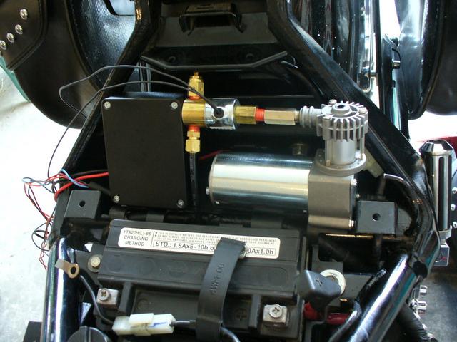
This photo and the next one show a dilemma I ran into (those not ordering the remote control option won't have this issue).
The instructions call for both the compressor and remote-control unit to mount under the seat. In order for that to work, they both must fit between the seat horns, or the seat won't install. These "horns" are the two parts of the frame that project upwards and to which your rear fender is bolted. (The remote control unit is the square black box to the left of the compressor in the photo). The instructions show this working just fine. However, the instructions also show a slightly different style compressor which apparently allowed that to work. My dilemma? With the compresor and remote control box in this kit, it is physically impossible (as far as I can work out) to fit them both between the seat horns so the seat will install correctly. In this photo you can see the remote box is under the seat horn, but the compressor is not. |
|
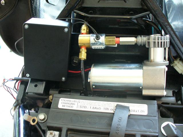
In this photo you can see the compressor is under the seat horn, but the remote box is not.
Solution? (at least the one I worked out)
Put the remote control box under the ride-hand side cover. |
|
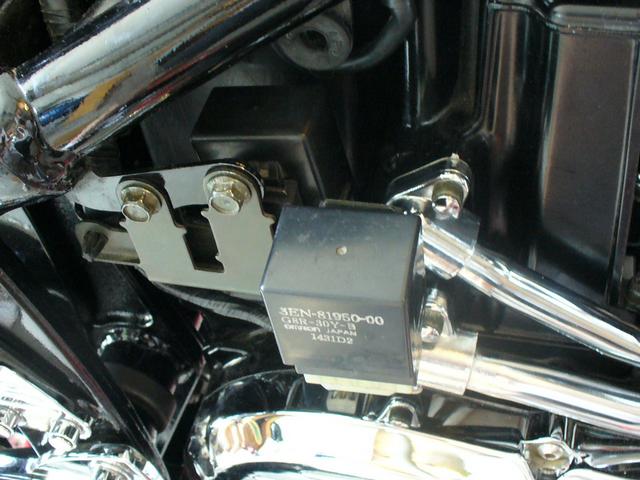
Here is what the stock set-up looks like under the right-hand side cover. Theres a bracket with two small black boxes attached. One of these is the starter relay. Not sure what the other one is. |
|
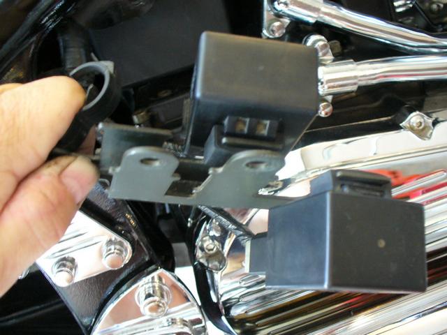
Here's the bracket they're mounted on, removed. |
|
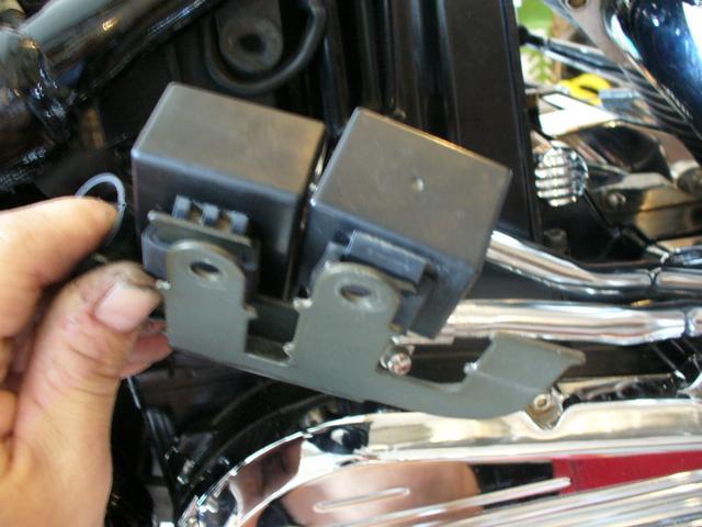
I needed a decent amount of space under the cover for the remote control box, so I had to move some things around.
I took the inner-most unit and moved it back to an open mounting spot on the bracket. Then I took the outer-most unit and moved it to the spot I just opened up by moving the last unit. |
|
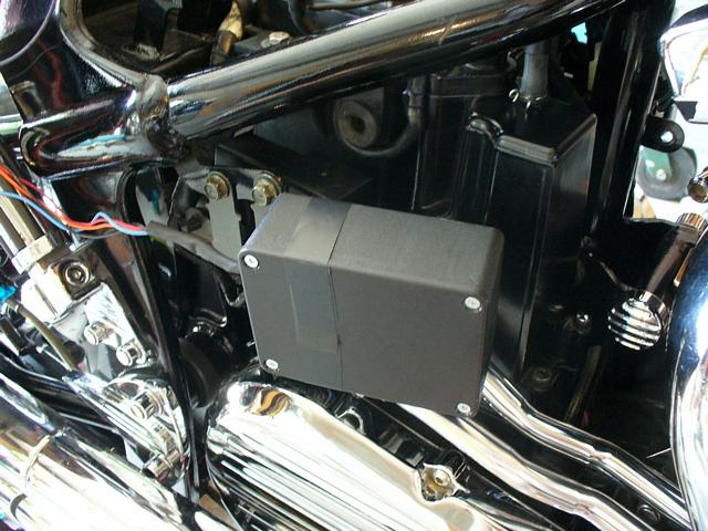
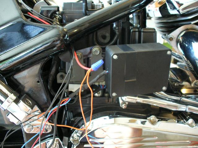
Then I simply mounted the remote control box to the outer part of the bracket (which now had nothing mounted on it) using electrical tape. Yeah...I know....that's a very unprofessional way to mount it. Why not drill and tap a hole on the back of the box for a mounting screw? I may do that eventually, but I also didn't want to make any openings into the box, allowing moisture in. |
|
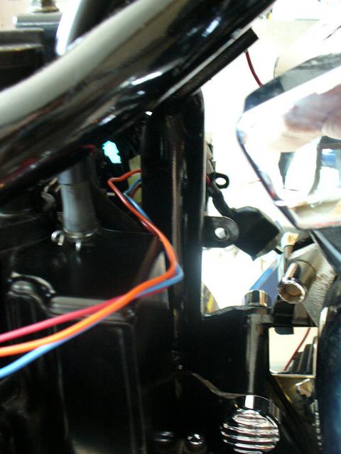
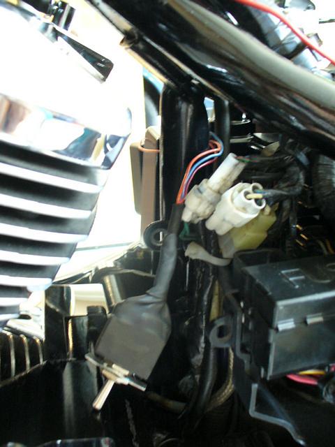
Now I had the problem that the wires from the compressor to the remote control unit were on the outside of the frame. I needed to get them on the inside. |
|
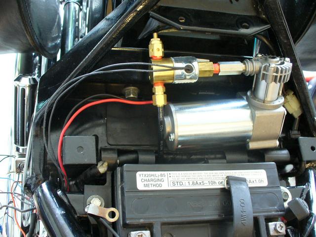
There were two wires coming from the compressor itself, and two wires coming from the selenoid (the small brass unit just above the compressor body where the air line mounts).
The wiring harness comes completely connected and asembled for operation. So, I very carefully removed the wire ties (one wire connection at a time), routed them inside the frame to under the right cover area, then put the wire ties back on to their correct connection (again....one wire connection at a time to avoid confusion).
|
|
My four wires are correctly routed, now it's time to organize the rest of the wires. |
|
I route the toggle switch and its wires over to the left side cover area. I don't want to have to reach down while on the bike to use the toggle and get my hands burned on the exhaust pipe, so I decide to put it on the left. It's a lot cooler over there! |
|
From the left side of the bike, you can see the toggle switch and its wires now routed. You're supposed to drill a hole in the side cover for the toggle switch to mount. If you don't order the remote control option, then this toggle is the only way to raise and lower the bike. For now, I decided I didn't want to drill a hole in good sheet metal if I didn't need to, and since I had the remote, that toggle is simply resting under my left side cover unused (for now). I may decide to mount it properly later. |
|
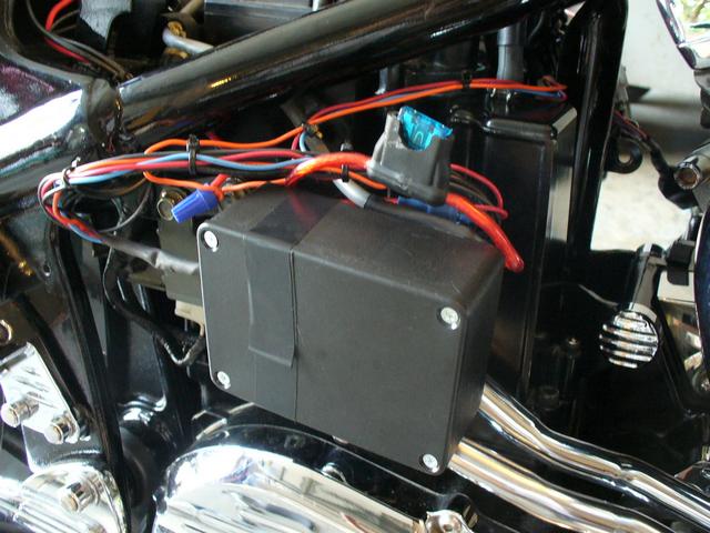
Here....all the rest of the wires are neatly zip-tied and tucked so there won't be any interference when putting the right side cover back on.
I situated the in-line fuse so it could be accessed easily. |
|
Last step before testing the unit is to connect the main power leads to the battery. You can see this in this photo, the large gray wire coming up from the right side cover and splitting the red to the positive battery terminal and the black to the negative battery terminal. (front of the bike is up in this photo)
|
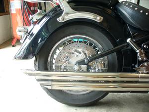
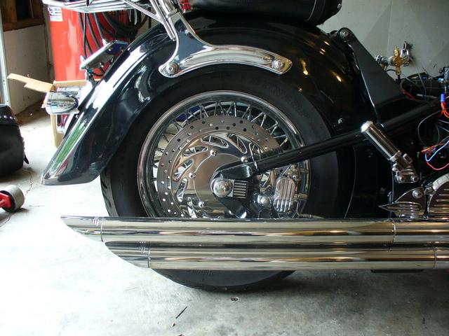
 Conservative - raised |
Now for the test of the conservative set-up. This is the raised level. Wow...that's much higher than even a stock set-up. Lots of daylight between fender and tire. |
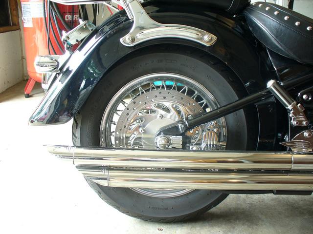
 Conservative - lowered |
Conservative set-up in its most lowered position. This is just a bit higher than what I had with the flip. It's not really what I'm looking for. Not low enough for a custom look. I want a real slammed look when I park the bike and put it in its most lowered position (as long as I can still get it decently high enough for 2-up riding and better cornering).
So.... time to change it to a more radical set-up. I decide to go to the other extreme for my two variables: If that ends up being too low, I'll use a set-up with something in between. |
 Radical - raised |
I don't have photos of the shock assembly in the more radical set-up (sorry). I didn't remove it completely from the bike. It was getting late in the day and I was a bit tired. So, I removed the rear bolt at the bottom of the relay, raised the rear control arm with a jack under the rear tire, dropped the rear of the assembly down, and made my changes. The front of the shock assembly was still attached to the frame up front.
|
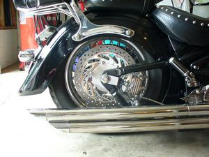
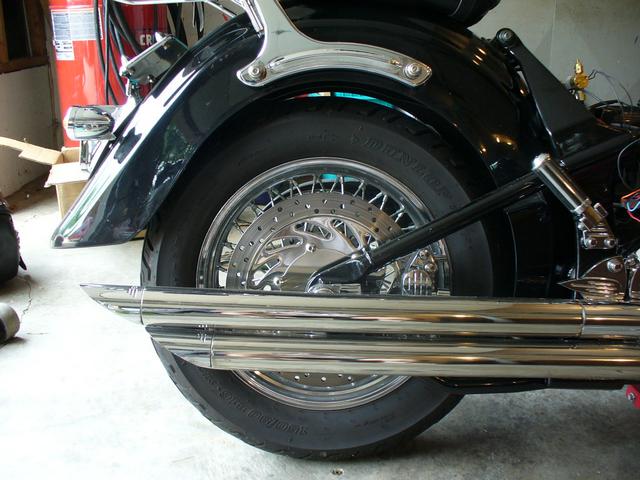
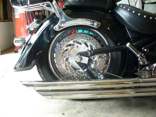 Radical - slammed! |
Most radical set-up in its lowered position. Now that is what I had in mind for slammed! The tire is stuffed nicely up under the fender for a more severe custom look.
This is where I've left the set-up for now. It's working out pretty good. I gave it a thorough run-through the following weekend riding four days in the Smoky Mountains and Blue Ridge Parkway. Even lowered, the ride is nice and firm. I can have it adjusted to the same level as when I had the stock shock and the "flip", but now, my bottoming out and scraping pipes/frame is almost nill compared to before. After riding about 500 miles on the set-up, my wife has no issues with the ride at all! Overall, I'm very pleased with the kit, the ride, and the look. It's a keeper! |
Home | Photos | "How To" | Links | Contact