Midnight Lightning
"How-To" Page
Modify your Nemesis for a Hypercharger Setup
Disclaimer: I can not be held responsible for anyone screwing up their Nemesis manifold in attempting this modification.
While it worked well for me, I can't guarantee other people's workmanship or prevent their mistakes.
You undertake this at your own risk!
Do you really want your leg to stretch that far around your breather?
If not, read on (but note the disclaimer).....
Adding a Hypercharger to your Roadstar adds a bit of additional bulk to your breather for your leg to get around.
Mounting that Hypercharger to a Nemesis manifold adds another 5/8" (15mm) to that already larger bulk.
If that Hypercharger is a Pro series, it adds yet another 1/2" over the normal Hypercharger!
|
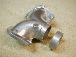
Modification #1 - of eventually 2 (shown below) October 2003
|
|
|
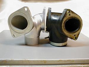
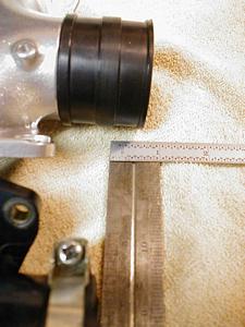
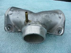
Another shot. I had read on the RSR forum that it caused any breather installed in the Nemesis to stick out 15mm (abt. 5/8") further than if mounted on the stock manifold. |
|
|
With the Nemesis-supplied rubber manifold-to-carb boot, you can see it does indeed stick out further. | |
|
Offset is 5/8 inch, just as I had read. |
|
|
There were forum posts describing how you can add 5/8" spacers to the Hypercharger (HC) brackets. But.... I wanted to use this manifold with a Hypercharger-Pro. A regular HC already sticks out a bit further than a stock breather. The HC-Pro adds another 1/2" over the regular HC. I certainly didn't want to have yet another 5/8 inch to this! At 5'8" tall, I don't have the long legs required to stretch around all this hunk of chrome sticking out on the right side of the bike. |
|
|
My buddy Brad Perkins (RSR: Longrider) had asked Nemesis (Glenn (?)) on the RSR when he was going to come out with some solution to this. The answer was less than desirable. It didn't appear anything would be done too soon, so....... I decided to modify the Nemesis eliminating the need for the 5/8" spacers. |
|
|
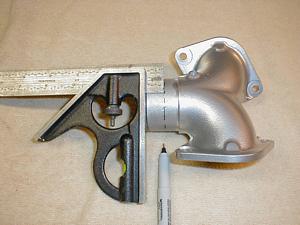
This would involve cutting off 5/8" from the Nemesis and it's rubber boot connector. Here, I'm marking off the 5/8" around the diameter of the manifold. |
|
|
Cutting the manifold with a normal hacksaw, very careful to keep it tracking vertical/perpendicular through the cut. | |
|
The removed piece. | |
|
Cut edge is now filed smooth. | |
|
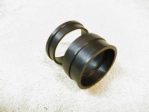
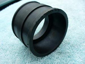
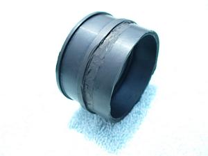
Now it's time to cut down the connector boot 5/8". Make sure to cut it off the end that is NOT close to the lip you see on the inside!! You want that inner ridge/lip to remain. It is a spacer/buffer between the manifold edge and carb edge. I'll refer to the end of the boot near the location of the inner lip as the 'front' of the boot (It will connect to the carb). I'll refer to the end furthest away from the inner lip as the 'back' of the boot (It will connect to the manifold). This photo is looking into the 'front' of the boot (showing the inner lip). |
|
|
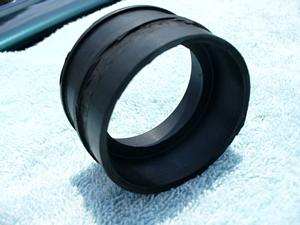
Using an exacto knife to very carefully cut the boot. This photo is looking into the 'back' of the boot. |
|
|
The removed 5/8" piece from the 'back' of the boot. Photo shows us looing into the 'front' of the boot again. |
|
|
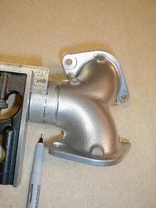
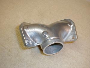
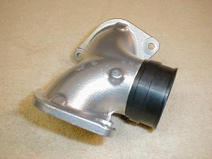
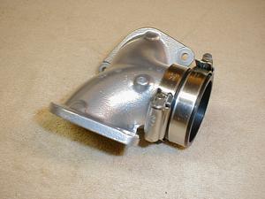
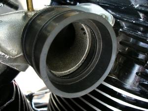
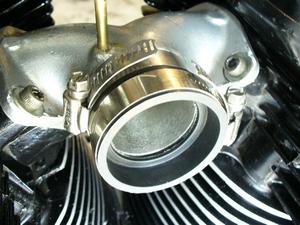
The cut boot on the cut manifold. |
|
|
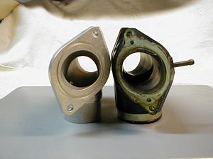
NOW the Nemesis is the same dimensions as the stock manifold. No need for 5/8" spacers | |
|
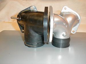
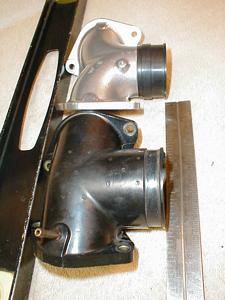
Lining them up for a final check | |
|
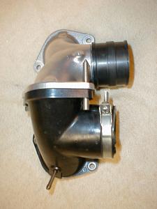
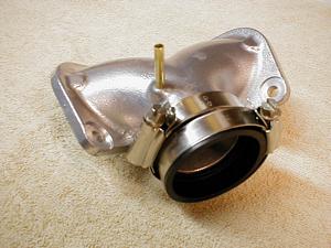
Assembly with clamps. | |
|
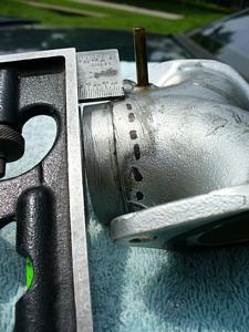
Because this application will use a Hypercharger, I needed a vacuum line to operate the HC's butterflies. So...I found tubing the same dimensions as on the stock manifold's set-up. It was either a hardware store, or hobby store (can't recall wich one was my source) Drill hole for a very tight fit. (can't recall the tubing or drill size). Use calipers or a micrometer to check both tube and drill, otherwise you'll end up with a hole too big, or too small. This modified manifold was mounted in late October 2003. |
|
|
Okay...if you're the engineering/thinking-ahead type of person, you may have noticed a potential problem in part of Modification #1, just shown to you.
|
||
|
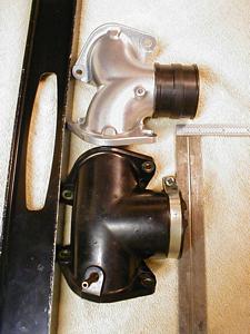
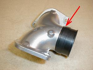
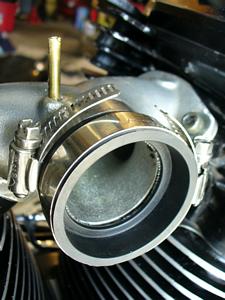
Modification #2 June 2006
If you re-look at the picture of the final cut boot on the cut manifold (shown here again on the left), you may have noticed that the area where the manifold-side clamp goes, is not entirely flat (doesn't have one singular outer diameter (OD) for the clamp to grip), and there wasn't a lot of lip left on the manifold to grab beneath it either. |
|
|
Results of this oversight:
1) Because of the less-than-optimal clamping effect at the manifold, I had to really tighten down on the clamp to get it to hold effectively. This cause the clamps to tear/bite its edge into the boot, yielding manifold boot tears. This gives you a manifold leak (too much air), and heavy backfiring on deceleration/downshifting.
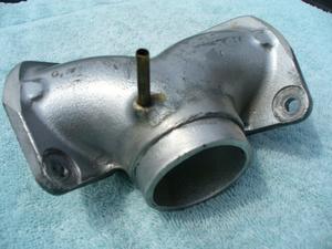
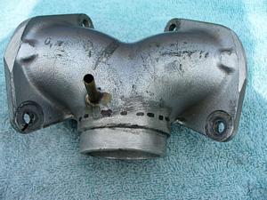
2) Because of the backfiring, sometime when starting the bike, a very strong backfire would actually 'blow' the carb or carb/boot right off the manifold! I just couldn't get the grip tight enough. I found myself on more than one occasion, actually having to remove the tank and remounting the boot and carb. (This was particularly embarrasing when it happened, of all places, in a Harley dealer's parking lot. Fortunately there were only a couple of people around.) I tried using thicker boots by modifying various rubber plumping connectors I easily found at Home Depot. These would work for a time, however, I still had biting/tearing problems. Ultimately, it seemed that the problem was because the manifold didn't have enough surface area for any boot to effectively clamp. So almost three years later I decide to mod the mod in order to gain a more optimal and even clamping force. June 2006. This is the original modified manifold after removing it from the bike. |
|
|
This photo shows that at some point during 2004 & 2005, I had slightly filed the upper edges of the Nemesis flange to make installation easier. It's a bear to get in otherwise and get the holes to line up. |
|
|
Ditto on the other flange. | |
|
There were two things to do to improve the clamping grip.... 1) Make a larger grip surface on the manifold, and 2) Try to provide one OD on the boot at the 'back', or manifold side.
Here I'm starting to resolve #1. |
|
|
Marked and ready to modify. | |
|
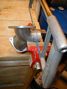
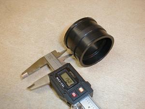
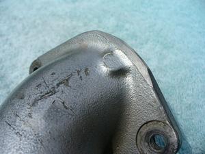
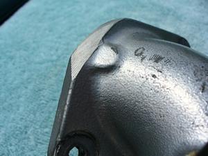
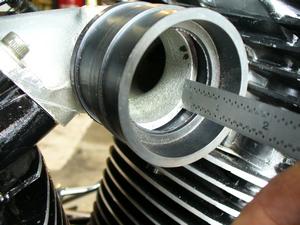
I mount the manifold in a bench vise to hold it steady while I remove metal (aluminum) back to the marked lines. To do this I use a drill motor with a combination of small, round metal remover bits and grinder bits (I use a Dremel too with similar styled bits). A rasp file, then a finer file. I use vernier calipers to check my progress. The goal is to get the diameter down to the same as the smaller OD, thereby gaining a larger clamping surface. This photo shows my final work. Just take your time. Aluminum is easy to work with, but it still takes awhile working around the various geometries of the manifold to do this. You don't want to accidentally grind off any of the mounting flanges of the manifold. |
|
|
I got me another stock Nemesis manifold boot (I believe I bought a couple of extras direct from Nemesis, their Missouri outlet (?)). | |
|
When mounted on my now modified-a-second-time manifold, you can see that the inner lip, which needs to be up against the manifold, is sticking out a bit. | |
|
Measure the gap, then use that actual measurement to cut off the 'back' (manifold-side) of the boot - like before. This will not necessarily be 5/8". It will be based on how much metal you removed from the manifold in this 2nd mod. So...measure before cutting! |
|
|
This time not only did I cut the measured portion off the 'back' of the boot, but I also very carefully and slowly trimmed off the larger OD using a flat razor blade, so that my 'rear' clamp had as close to a singular OD to grip as possible.
This photo is looking into the 'back' of the cut and trimmed boot.
You can see my less than perfect trimming on the OD. I just got it as close as I could without slicing my fingers in the process. |
|
|
Another photo looking into the 'back' of modified boot. |
|
|
Now, the modified boot fits correctly with that smaller inner lip up against the manifold like it's supposed to be. | |
|
Clamps are on and ready for the carb to be installed!
So far this has worked great (it's been one year). |
|
Home | Photos | "How To" | Links | Contact